

Ask a New Question
Design Support
If you need one-on-one support for confidential technical issues with your project, please click on "Contact Us" below.

jwillick
I am trying to communicate with the GT911 touch controller that is in the Raspberry Pi 2 display panel
https://www.raspberrypi.com/products/touch-display-2/
the touch controller IC is not responding to polling and is not detected but the same I2C bus is working for the backlight controller. I did some probing and found that even though it has a 10k pullup on the GT911 the reset pin is still stuck low. Is the chip damaged or what could cause this? I am powering AVDD28 and VDDIO with 3.3V. AVDD18 and DVDD12 just have decoupling caps. AVDD18 measures 0V and DVDD12 measures 1.4V, not sure if that is expected or not.
Also I am not using the interrupt pin
any suggestions or help would be greatly appreciated.
thank you
lde****.au
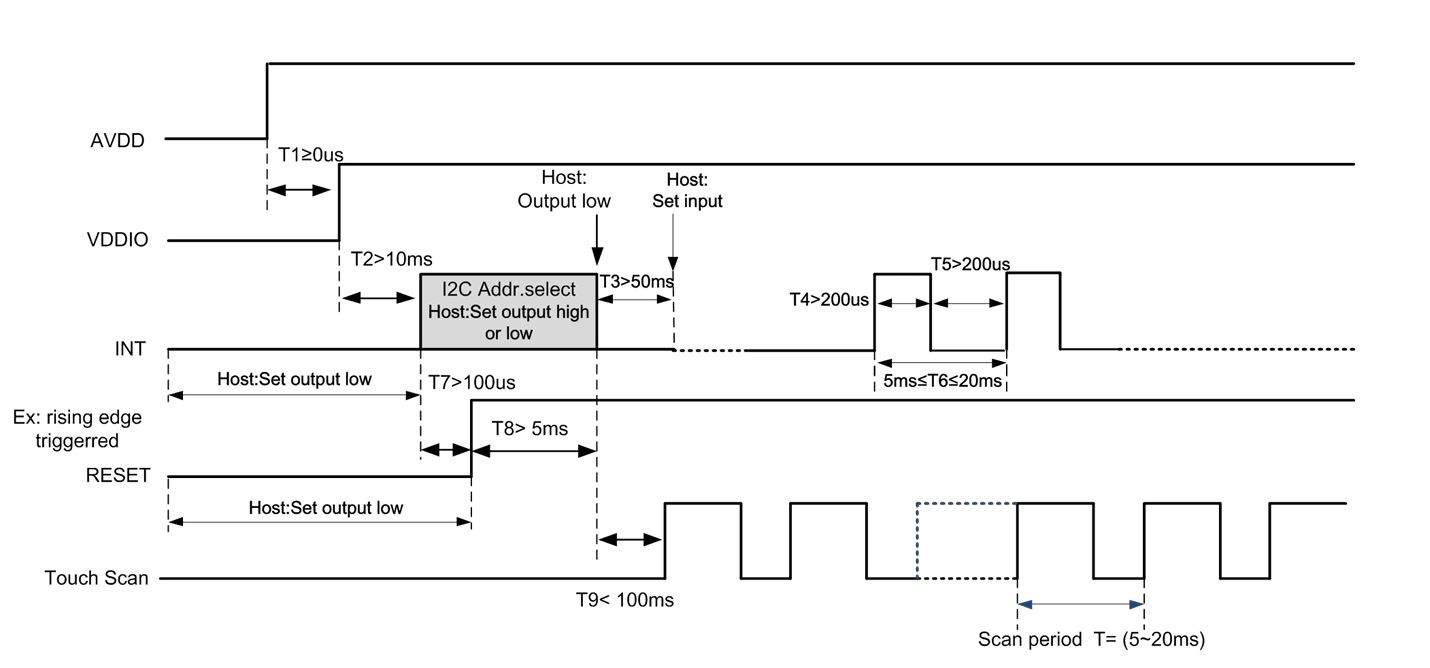
That is in the manual you have to use the INT pin .. it is part of the reset sequence
Look at section 4.1 Power-On Timing of GT911
You can choose to ignore the INT pin after the reset but you must control it during reset.
Likely the GT911 is at the alternative address or it hasn't reset at all.
jwillick
thanks for your help, for background, I am using the Raspberry Pi 2 display panel: https://www.raspberrypi.com/products/touch-display-2/
I am not sure if you are aware but this panel uses your driver. It is working for me when plugged into a Raspberry Pi device but when I plug it into my hardware I can't figure out why it does not work.
I did some probing to compare and found a couple of differences:
when using the RPi device the pin AVDD18 is low, is this pin an output? does the kit have a built in 1.8V LDO? why would it be off?
also the reset pin is stuck low even though its hard pulled up with a 10k to 3.3V, its like the chip is off and not happy. The interrupt line is also not connected on the RPi 2 panel but that seems to be fine so I don't know what might be wrong. The supply is 3.3V/3.2V and seem to be up and ok.
I am a little stumped what we could be doing that is causing it to be stuck. A small delta I noticed is that in our kit the I2C lines have 2.2k pullups to 3.3V. On the Raspberry Pi device the I2C is pulled up to 2.3V for some reason.
Also note that VDDIO is 3.3V in both cases
thanks for your help
Jonathan
lde****.au
Again read the datasheet .... The controller is locked in reset ... AVDDIO goes high after reset ... IT'S ON THE DATASHEET
You need exact RESET LINE timing and why the RESET LINE IS USUALLY DRIVEN. I guess if your hardware lacks that ability you would need to calculate a cap to go with your resistor with at least 10ms time constant on the reset line and pray.
Here is your timings

Open WeChat, use "Scan" to follow.


